15 DC Circuits

Delight – a web-based board game on electricity

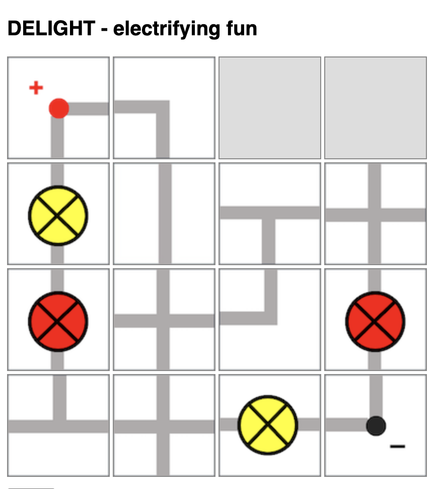
I had previously shared about this physical board game that I designed to teach electricity concepts. Now, with ChatGPT’s help, I have managed to produce a simple implementation of the board game so that there is no need to print and cut out the pieces anymore.

However, the game is still unable to detect if the light bulb will light up and automatically change the image colour or add the scores. That will require further complex programming due to the many possible outcomes for this game.

https://physicstjc.github.io/sls/delight/index.html

The rules of the game are as such:

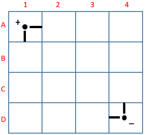
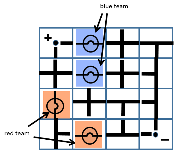
  1. Players will take turns to connect their own bulbs to the terminals while trying to sabotage their opponent’s bulbs.
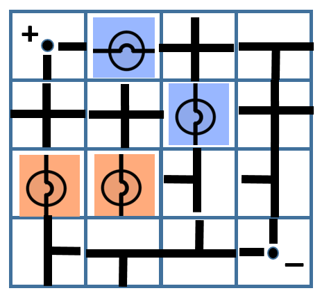
  2. Players will take turns to place one piece on the 4-by-4 game board by clicking to select the electrical component and clicking on the square on the board to place it.
  3. Upon placing the piece, the player can also turn that piece in any orientation (by clicking on it) within the same turn.
  4. Players can choose to use up to two turns at any point in the game to rotate any piece that had been placed by any player.
  5. In other words, each player has 9 turns: 7 placement turns and 2 rotation turns.

At lower levels, students can compete to see who has the most lit bulbs. However, they will need to be able to identify which light bulbs are lit. Do watch out for short-circuits.

At higher levels, students can compete to see whose light bulbs has the most total electrical power, with some calculations involved.

Internal Resistance and Terminal Potential Difference

https://www.geogebra.org/m/puvfjxk5

This applet demonstrates how terminal potential difference (as measured by the voltmeter across the terminals of the battery) changes depending on :

  1. internal resistance r
  2. external resistance R
  3. emf E
  4. when a switch is turned on and off
<iframe scrolling="no" title="Internal Resistance and Terminal Potential Difference" src="https://www.geogebra.org/material/iframe/id/puvfjxk5/width/640/height/480/border/888888/sfsb/true/smb/false/stb/false/stbh/false/ai/false/asb/false/sri/false/rc/false/ld/false/sdz/false/ctl/false" width="640px" height="480px" style="border:0px;"> </iframe>

Potential Divider with Thermistor Applet

The wonderful thing about GeoGebra is that you can whip up an applet from scratch within an hour just before your lesson and use it immediately to demonstrate a concept involving interdependent variables. I was motivated to do this after trying to explain a question to my IP4 students.

The RGB colours of the thermistor reflects the temperature (red being hot, bluish-purple being cold)

https://www.geogebra.org/m/etszj23m

This was done to demonstrate the application of potential dividers involving a thermistor and a variable resistor. It can, of course, be modified very quickly to introduce other circuit components.

Geogebra App on Maximum Power Theorem

GeoGebra link: https://www.geogebra.org/m/hscshcj8

This simulation demonstrates the power dissipated in a variable resistor given that the battery has an internal resistance (made variable in this app as well).

Since the power dissipated by the resistor is given by

[latex]P=I^2R[/latex]

and the current is given by

[latex]I=E(R+r)[/latex],

[latex]P=E^2\times\dfrac{R}{(R+r)^2}=\dfrac{E^2}{\dfrac{r^2}{R}+R+2r}[/latex]

This power will be a maximum if the expression for the denominator [latex]\dfrac{r^2}{R}+R+2r[/latex] is a minimum.

Differentiating the expression with respect to R, we get
[latex]\dfrac{d(\dfrac{r^2}{R}+R+2r)}{dR}=-\dfrac{r^2}{R^2}+1[/latex]

When the denominator is a minimum,
[latex]-\dfrac{r^2}{R^2}+1=0[/latex]

Therefore,
[latex]r=R[/latex] when the power dissipated by the resistor is highest.

Geogebra Simulation of a Potentiometer

Some of the more challenging problems in the topic of electricity in the A-level syllabus are those involving a potentiometer. The solution involves the concept of potential divider and the setup can be used to measure emf or potential difference across a variety of circuits components. Basically, students need to understand the rule – that the potential difference across a device is simply a fraction of the circuit’s emf, and that fraction is equal to the resistance of the device over the total resistance of the circuit.

[latex]V_{device}=\frac{R_{device}}{R_{total}}*emf[/latex]

The intention of this Geogebra app is for students to practise working on their calculations, as well as to reinforce their understanding of the principle by which the potentiometer works.

GeoGebra link: https://www.geogebra.org/m/pzy3qua8

DeLight Version 2

I modified “DeLight”, the board game that I designed a few years back into a worksheet version (for small groups) as well as a powerpoint version (that teacher can facilitate as a class activity, pitting half the class against another).

Worksheet: DOWNLOAD

Slides: DOWNLOAD

The objectives of the game is to reinforce concepts related to D.C. Circuits such as:

  1. Sum of potential difference (p.d.) across parallel branches of a circuit is the same.
    $$E = V_1 + V_2 + V_3 +…$$
  2. P.d. across a device is given by the ratio of resistance of device to total resistance multiplied by emf (potential divider rule)
    $$V_1 = \dfrac{R_1}{R_{total}}\times E$$
  3. Brightness of light bulb depends on electrical power
    $$P = IV = \dfrac{V^2}{R} = I^2R$$
  4. Current can bypass a device via a short-circuiting wire.

The worksheet and powerpoint slides contain a few examples that allow discussion on the above concepts based on some possible gameplay outcomes. For example, the following is a game where the blue team wins because the p.d. across each blue light bulb is twice that of the p.d. across each red light bulb.

In the following scenario, the game ended in a draw. Students may not be able to see it immediately, but the blue light bulb with a vertical orientation is actually short-circuited by the vertical branch on its right.

Feel free to use and/or modify the game to suit your own class needs.