IP3 03 Dynamics

Use of System Schema to Visualise Action-Reaction Pairs

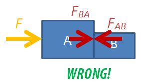
It is a common misconception for students to assume that when a book is placed on a table, its weight and the normal contact force acting on it are action-reaction pairs because they are equal in magnitude and opposite in direction.

While we can emphasise the other requirements for action-reaction pairs – that they must act on two different bodies and be of the same type of force – I have tried a different approach to prevent this misconception from taking root. After reading this article on the use of the system schema representational tool to promote understanding of Newton’s third law, I tried it out with my IP3 students.

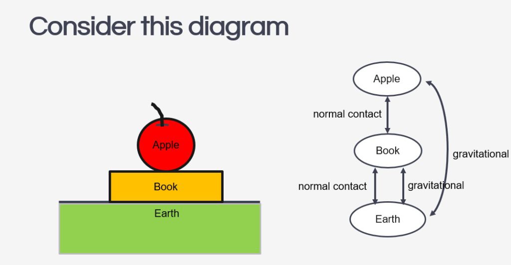
The system schema identifies the bodies in a question and represents them with shapes detached from each other to give space to draw the connecting arrows between them. The arrows must be labelled with the type of force, either by coding them (e.g. r for reaction force, g for gravitational force) or in full.

Every force will be drawn as a double-headed arrow between two bodies to represent that they are action-reaction pairs. It is important for students to understand that every force in the universe comes in such a pair, and the system schema can help them visualise that. If there is a force without a partner, it just means the system is not in the frame yet.

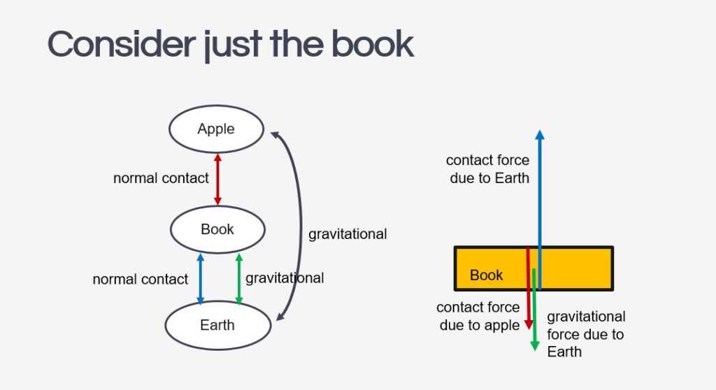
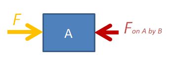
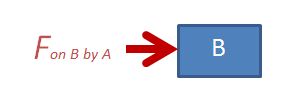
The next step to using the system schema is for students to isolate the object in question and draw its free-body diagram. Each force vector in the diagram should be accompanied by a name that includes: 1. the type of force and 2. the subject which exerts that force on the object.

The effectiveness of this method of instruction is clearly presented in the paper mentioned above, as performance on the force concept inventory’s questions on the third law saw an improved average from 2.8 ± 1.2 to 3.7 ± 0.8.

Unequal masses attached to rod in free fall

Came across a question recently that many students answered incorrectly.

Close to the surface of the Earth the gravitational field strength is uniform. A pair of unequal masses are joined by a light, rigid horizontal bar and suspended by a string from their centre of gravity as shown. The mass M of the ball on the left is larger than the mass m of the ball on the right.

The supporting string is now cut and the system begins to fall. Air resistance is negligible.

Which statement is correct?

AThe bar will remain horizontal as it falls.
BThe bar will rotate clockwise as it falls.
CThe bar will rotate anti-clockwise as it falls.
DThe bar will first rotate clockwise and then rotate anticlockwise as it falls.

Without air resistance

This question supposes that air resistance is negligible and so the only forces initially acting on the object is weight. The answer that many students gave incorrectly as B because they assume that the larger weight acting on the larger mass will bring about a larger acceleration.

Since the object begins in equilibrium, and the acceleration of both objects is just gravitational acceleration, the bar will remain horizontal.

With air resistance

This then invites a question: What if there is air resistance?

To consider the vertical acceleration on both balls, we need to consider the net force $F_{net}$, which is the vector sum of weight $W$ and air resistance $F_R$, ignoring the tension exerted by the rod at the initial stage of the fall.

$$F_{net} = W – F_R = V \rho_{ball}g – \dfrac{1}{2} \rho_{air}v^2C_DA$$

The volume V of a sphere is proportional to $r^3$ and its cross-sectional area A is proportional to $r^2$,

A larger radius will imply a larger increase in V than A, and hence, a large $W$ than $F_R$. This will then allow the larger mass to experience a larger acceleration than the smaller mass in the initial stage.

Man in Elevator

I just took the elevator in my apartment building with the PhyPhox mobile app and recorded the acceleration in the z-direction as the lift went down and up. This was done in the middle of the night to reduce the chances of my neighbours getting into the elevator along the way and disrupting this experiment, and more importantly, thinking I was crazy. The YouTube video below is the result of this impromptu experiment and I intend to use it in class tomorrow.

I used to do this experiment with a weighing scale, and a datalogger, but with smartphone apps being able to demonstrate the same phenomenon, it was worth a try.

To complement the activity, I will be using this simulation as well. Best viewed in original format: https://ejss.s3.ap-southeast-1.amazonaws.com/elevator_Simulation.xhtml, this simulation done in 2016 was used to connect the changes in acceleration and velocity to the changes in normal contact force as an elevator makes its way up or down a building.

Newton’s 2nd Law Applet

For a full-screen view, click here.

<iframe scrolling="no" title="Dynamics Problem" src="https://www.geogebra.org/material/iframe/id/uthszwjq/width/640/height/480/border/888888/sfsb/true/smb/false/stb/false/stbh/false/ai/false/asb/false/sri/false/rc/false/ld/false/sdz/true/ctl/false" width="640px" height="480px" style="border:0px;"> </iframe>

This applet was designed with simple interactive features to adjust two opposing forces along the horizontal direction in order to demonstrate the effect on acceleration and velocity.

Newton’s 2nd Law Questions

Here are the steps to solving a problem involving Newton’s 2nd law.

Step 1: Draw a free body diagram – where possible, sketch a free body diagram to represent:

  1. the body isolated from other objects
  2. the forces acting on the body (ignore all internal forces) along the line of motion.
  3. the direction of acceleration.

Step 2: Write down the equation: $$F_{net}=ma$$

Step 3: Add up the forces on the left-hand side of the equation, making sure that forces acting opposite to the direction of acceleration are subtracted.

Step 4: Solve the equation for the unknown.

For example,

A horizontal force of 12 N is applied to a wooden block of mass 0.60 kg on a rough horizontal surface, and the block accelerates at 4.0 m s-2. What is the magnitude of the frictional force acting on the block?

Step 1: Free-body diagram

Newton's 2nd law

Step 2: Write down the 2nd law equation

By Newton’s 2nd law, $$F_{net}=ma$$

Step 3: Add up the forces making up the net force

$$12 – f = 0.60 (4.0)$$

Step 4: Solve for unknown

$$ f = 12 – 2.4 = 9.6 N$$

Free-Body Diagrams in Two-Body Motion


Students are often confused about the forces in drawing free-body diagrams, especially so when they have to consider the different parts of multiple bodies in motion.

Two-Body Motion

Let’s consider the case of a two-body problem, where, a force F is applied to push two boxes horizontally. If we were to consider the free-body diagram of the two boxes as a single system, we only need to draw it like this.

two-body
Considering both boxes as a single system

For the sake of problem solving, there is no need to draw the normal forces or weights since they cancel each other out, so the diagram can look neater. Applying Newton’s 2nd law of motion, $F=(m_A+m_B) \times a$, where $m_A$ is the mass of box A, $m_B$ is the mass of box B, F is the force applied on the system and a is the acceleration of both boxes.

You may also consider box A on its own.

DYNAMICS2
Considering box A on its own

The equation is $F-F_{AB}=m_A \times a$, where $F_{AB}$ is the force exerted on box A by box B.

The third option is to consider box B on its own.

DYNAMICS3
Considering box B on its own

The equation is $F_{BA}=m_B \times a$, where $F_{BA}$ is the force exerted on box B by box A. Applying Newton’s 3rd law, $F_{BA}=F_{AB}$ in magnitude.

Never Draw Everything Together

NEVER draw the free-body diagram with all the forces and moving objects in the same diagram, like this:

wrong freebody diagram

You will not be able to decide which forces acting on which body and much less be able to form a sensible equation of motion.

Interactive

Use the following app to observe the changes in the forces considered in the 3 different scenarios. You can vary the masses of the bodies or the external force applied.

Multiple-Body Problems

For the two-body problem above, we can consider 3 different free-body diagrams.

For three bodies in motion together, we can consider up to 6 different free-body diagrams: the 3 objects independently, 2 objects at a go, and all 3 together. Find the force between any two bodies by simplifying a 3-body diagram into 2 bodies. This trick can be applied to problems with even more bodies.