18 Electromagnetic Induction

AC Generator Simulator

Open in new tab 🔗

An AC generator, or alternator, is a device that converts mechanical energy into electrical energy by means of electromagnetic induction. At its core, the generator consists of a coil of wire that is made to rotate within a magnetic field. This magnetic field is usually produced by permanent magnets or electromagnets positioned so that their field lines pass through the area enclosed by the coil.

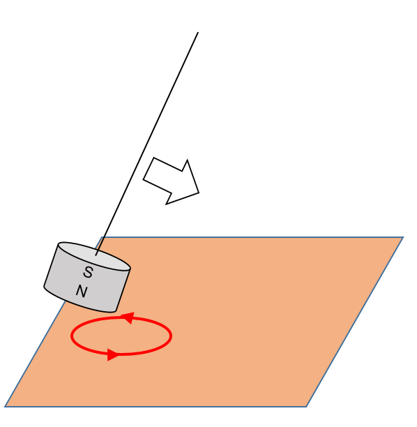
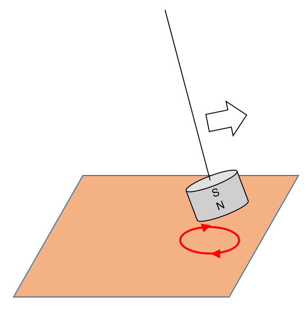
As the coil rotates, it cuts through the magnetic field lines. This motion causes the magnetic flux linkage through the coil to change over time. According to Faraday’s Law of Electromagnetic Induction, whenever there is a change in magnetic flux linkage through a circuit, an electromotive force (emf) is induced in the circuit. The faster the coil rotates or the stronger the magnetic field, the greater the rate of change of flux, and thus, the greater the induced emf.

The rotation causes the magnetic flux to vary in a sinusoidal manner, leading to an emf that also varies sinusoidally. This means the direction of the induced current reverses every half-turn, producing an alternating current (AC). The expression for the induced emf is typically given by: ϵ(t)=NBAωsin(ωt)

where N is the number of turns in the coil, B is the magnetic flux density, A is the area of the coil, ω is the angular velocity of rotation, and t is time.

To extract the current from the spinning coil without tangling wires, slip rings are connected to the ends of the coil. These rotate with the coil and maintain contact with carbon brushes, which allow the generated current to flow into an external circuit.

In essence, an AC generator works by continually rotating a coil within a magnetic field, causing a periodic change in magnetic flux that induces an alternating voltage. This principle is the foundation of electricity generation in power stations around the world.

Faraday’s Experiment Simulation

Open in new tab 🔗

In Faraday’s experiment, moving a magnet into or out of a coil induces an electric current, which is detected by a galvanometer. The faster the magnet moves, the greater the deflection of the needle. The direction of needle deflection depends on whether the magnet is moving toward or away from the coil—reversing as the direction of motion changes. When the magnet is stationary, the needle returns to the center, indicating no induced current.

This simulation allows the user to explore the laws of electromagnetic induction (Faraday and Lenz) by dragging a magnet into and away from a coil.

Braking of a Magnetic Pendulum with Copper Plate

In this video, we will observe how induced eddy currents in a copper plate slow down a magnetic pendulum. 

When the pendulum is set in motion, it usually oscillates for quite a while. This pendulum consists of a strong magnet.

If we slide a copper plate underneath the magnet while it is in motion, the magnet comes to a stop quickly. Note that copper is not a ferromagnetic material, which means it does not get attracted to a stationary magnet.

As the magnet moves across an area on the copper plate, the change in magnetic flux induces eddy currents on the plate. These eddy currents flow in such a way as to repel the magnet as it approaches the plate and attracts the magnet as it leaves the plate, therefore slowing the magnetic pendulum.

Eddy currents repels the magnet as it approaches
Eddy currents attracts the magnet as it leaves

When we pull the copper sheet out from under a stationary magnetic pendulum, the eddy currents will flow in such a way that it becomes attracted to the copper sheet.

Moving the copper sheet to and fro at a certain frequency (the pendulum’s natural frequency), the magnetic pendulum can be made to oscillate again.

Simulation: Faraday’s Law of Induction

This simulation traces the flux linkage and corresponding emf generated by a rectangular coil rotating along an axis perpendicular to a uniform magnetic field. One is able to modify the angular frequency to see the effect on the frequency and peak emf generated.

Faraday’s law of electromagnetic induction

https://ejss.s3-ap-southeast-1.amazonaws.com/faradayslaw_Simulation.xhtml

Simulation: How emf is generated

https://ejss.s3-ap-southeast-1.amazonaws.com/emf_Simulation.xhtml

This simulation is really more of an animation that allows students to apply Fleming’s left hand rule on a line of electrons along a conductor cutting a magnetic field in order to appreciate how emf is generated.

EMF of A.C. Generator

For my students to discuss. Please leave your answer and explanation in the comments below. Options are:

A. V0 (peak voltage)
B. Vo2
C. Zero
D. None of the above