17 Electromagnetic Forces

3D view of forces on parallel currents using GeoGebra

Open in new tab 🔗

The simulation serves to show how the magnetic field of one current-carrying wire exerts a force on another current-carrying wire.

When two wires are placed parallel to each other and carry electric currents, each wire produces its own magnetic field. The magnetic field around a straight current-carrying conductor forms concentric circles, and the direction of these circles can be determined by the right-hand grip rule: if you point your thumb along the direction of the current, your curled fingers show the direction of the magnetic field lines.

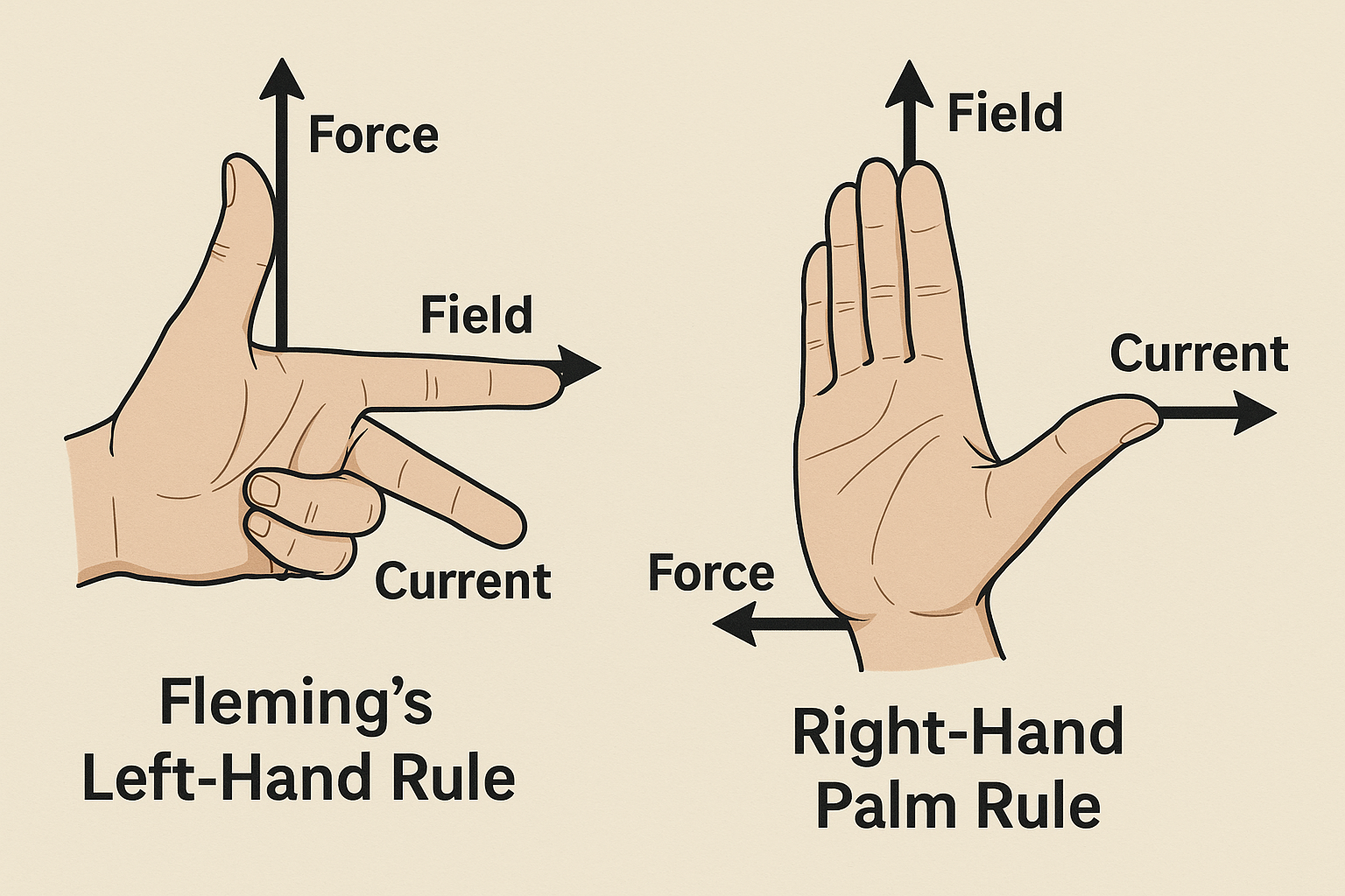
Because of this, one wire is always sitting inside the magnetic field created by the other. The moving charges in the second wire—that is, the current—interact with this magnetic field and experience a force. The strength of the force depends on the current in both wires and the distance between them, while the direction of the force can be worked out using Fleming’s left-hand rule or simply by considering how the two fields interact.

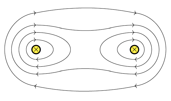
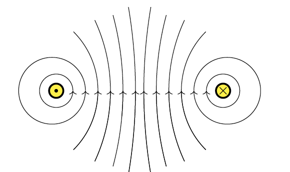
Magnetic field patterns between two parallel currents interact in such a way as to form either an attraction (for currents in same direction) or a repulsion (for opposite currents)

If the currents in the two wires flow in the same direction, the magnetic fields between the wires reinforce each other, producing a stronger field outside the pair and a weaker field between them. This imbalance pulls the wires towards each other, so they attract. On the other hand, if the currents run in opposite directions, the magnetic fields between the wires reinforce instead, while the fields outside are weakened. The result is a pushing apart of the two wires, so they repel each other.

In short, the force on parallel wires arises because each wire generates a magnetic field that acts on the current in the other. Identifying the force is straightforward once you know the directions of the currents: currents in the same direction cause attraction, while currents in opposite directions cause repulsion.

Fleming’s left-hand rule vs right-hand palm rule

Fleming’s Left-Hand Rule and the Right-Hand Palm Rule are visual tools used to predict directions in electromagnetic interactions.

Fleming’s Left-Hand Rule applies to electric motors and helps determine the direction of the force (motion) on a current-carrying conductor placed in a magnetic field. By aligning the thumb (force, $F$), first finger (magnetic field, $B$), and second finger (current, $I$) at right angles, one can deduce the force direction.

The Right-Hand Palm Rule serves the same purpose, but might actually be more intuitive, as the fingers would look like parallel vectors in a uniform magnetic field. The thumb points in the direction of the current. The hand will then naturally look like it is exerting a push in the direction of the palm.

I like to joke with my class that both serve the same purpose but one resembles a gun while the other resembles a kungfu move. Which would you prefer?

Side note: The image above is generated using a single prompt with ChatGPT 4o: “draw an image representing fleming’s left hand rule, next to the right-hand palm rule.” I’m impressed by how far AI image generation has come.

Movement of charged particle in parallel E and B fields

Access via https://www.geogebra.org/m/erehat7n for a full-screen view.

Videos on Electromagnetism

This is a post that exists simply to park the YouTube videos that I might need to use during a JC2 lecture on Electromagnetism.

Magnetic Force on a Current-Carrying Conductor

Using a neodymium magnet, some paper clips and a battery, you can demonstrate the magnetic force acting on a current-carrying wire while recalling Fleming’s left-hand rule. Using the same frame constructed in the previous video, you just need to add a wire with a few bends in between to create a U-shape in the middle as shown in the picture below. A small piece of insulating tape (you can use any adhesive tape) is added to one end of the wire to show the original dangling position of the U-shape before current flows through it. Be sure to leave some space at the end with the insulating tape for you to switch on and off the current by pushing that end in and out.

With the south pole facing up and the current flowing from right to left, the magnetic force acts towards you.

When the insulating tape touches the paper clip, current stops flowing and there is no magnetic force.

With the south pole facing up and the current flowing from right to left, the magnetic force acts away from you.


Building a Simple DC Motor

Using material that is easily available, you can build a simple homopolar D.C. motor (one that uses a single magnetic pole. I made the video above to help you do so.

The material used are as follows:

  1. insulated copper wire
  2. paper clips
  3. neodymium magnet
  4. 1.5V AA battery
  5. plastic or wooden block (I used a 4×2 Lego block)
  6. scissors
  7. permanent marker
  8. adhesive tape

The steps involved are:

  1. Attaching the magnet on the side of the battery using a long piece of adhesive tape and sticking both of them onto the Lego block. The polarity of the magnet does not matter.
  2. Next, we need to shape one end of each paper clip so as to make it longer and to make a small loop at the top. The paper clips are then fixed on the ends of the battery using adhesive tape.
  3. Coiling wire can be done with the help of a round cylindrical object such as a marker. Roughly 10-15 coils will do.
  4. The ends of the wire can used to bundle the coils together. Make sure they are tied up tightly.
  5. Since we are using an insulated wire (otherwise the current will just go straight from one paper clip to another without passing through the coils), we need to scrape of the insulation at the ends using either sandpaper or the edge of a pair of scissors.
  6. Using a permanent marker, we can colour one side each end in order to insulate that side. This will prevent current from flowing through the loops for half of every cycle. It has the same effect as that of a commutator.
  7. Finally, we will mount the coils onto the two paper clips and allow the motor to spin.

Do take note that the motor should not be left connected to the battery for too long as it will drain the battery very quickly and generate a lot of heat in the process.

How this can be used for the O-level/A-level syllabus

Teachers can use this as a demonstration that shows the motor effect of a current in a wire placed in a magnetic field, as well as to apply Fleming’s left-hand rule.

One can also make an second coil without insulating half the surface of the points of contact with the paper clips to show the importance of the commutator in a DC motor. The coil will simply oscillate to and fro due to the change in direction of the magnetic force on the lower half of the loop every half a turn.