17 Electromagnetic Forces

Homopolar Motor 1

A homopolar motor is a simple electric motor that does not require the use of a commutator. The electric current flows in a fixed direction within the wires of the motor. The following are instructions on how to construct this simple teaching tool that can be used to demonstrate how a motor works, as well as teach concepts such as Fleming’s left-hand rule and $$\mathbf{F}= I\mathbf{l \times B}$$.

Materials

  1. Copper wire (about 22 cm)
  2. Small neodymium magnets (1 or 2)
  3. 1.5 V AA-size battery
  4. Base with either another magnet or a iron surface, such as the head of an iron nail

Procedure

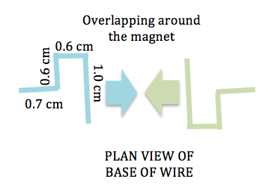
  1. Make a V-shaped bend in the middle of the copper wire, with about 0.5 cm on both sides of the V-shape. Bend the copper wire into a rectangular loop using the dimensions shown below. Homopolar Motor Diagram
  2. Tip: You may use the edge of a wooden block as a guide to bend the copper wires at right angles. A pair of wooden blocks can also be used to flatten the rectangular loop if you press them together tightly with the loop in between.
  3. Mount the neodymium magnet(s) onto the magnet or iron base.
  4. Hook the wires at the base around the magnets.
  5. Place the AA-sized battery with the protruding end on the magnet(s).
  6. Complete the electric circuit by placing the V-shaped end of the rectangular loop onto the flat end of the battery and watch the loop spin.
  7. Be careful not to keep the current flowing for too long as the battery and wire can get very hot.

Science Explained

  1. A force acts on a current if it is placed in a magnetic field. This force is what causes the motor to spin about its axis.
  2. To apply Fleming’s left hand rule, observe from the diagram below how the magnetic field bends around the magnet and its direction with respect to the direction of current flow. How do you think the loop will spin?homopolar motor field lines

If you are having difficulty making this version of the homopolar motor, try the other design for the homopolar motor made using a screw.

Electromagnet

Materials

  1. Insulated wire (about 1 m in length)
  2. Iron nail (at least 5 cm in length)
  3. 1.5 V battery
  4. Adhesive tape
  5. Small metal paper clip

Procedure

  1. Test that the iron nail is not already magnetised by trying to pick up the metal paper clip with it.
  2. Strip the two ends of the wire off its insulation. Leave about 1 cm bare on each end.
  3. Coil the wire around the iron nail, pushing each coil tightly together, to make a solenoid. Make sure you leave about 5 cm free at each end of the wire in order to connect the battery to the solenoid.
  4. If there is excess wire, make a second layer of coils around the first layer.
  5. Connect the ends of the wire to the terminals of the battery.
  6. Test the solenoid now by picking up the paper clip.

Oersted’s Experiment

Hans Christian Oersted showed that an electric current can affect a compass needle in 1820. This confirms the direct relationship between electricity and magnetism, which in turn, paved the way for further understanding of the two. The direction of the magnetic field can be changed by flipping the wire around, which suggests that the direction of the magnetic field is dependent on the direction of current flow.

Materials

  1. 1.5V Battery
  2. Wire
  3. Compass

Procedure

  1. Place the compass on a horizontal surface.
  2. Connect the wire to both ends of the battery.
  3. Place the middle of the wire directly over the compass, parallel to the initial orientation of the needle.
  4. Observe the needle deflect to one direction.
  5. Now flip the wire over so the current flows in the opposite direction and place it over the compass again.
  6. The needle will deflect in the other direction.
  7. Additionally, you can place the compass on top of the wire now.

Science Explained

A current will carry with it its own magnetic field. The magnetic field lines form concentric circles around the wire so that the field points in one direction above the wire and the opposite direction below the wire. Using the right-hand grip rule, where one holds his hands as though he is gripping something with his thumb pointing in the direction of current flow, his fingers will curl in a way as to indicate the direction of the magnetic field. This is also the direction in which the needle deflects.