16 Feb 2013 - Seng Kwang Tan 17 Electromagnetic Forces
I enjoy lecturing on topics like Superposition and Electromagnetism in the GCE A-level syllabus as they lend themselves well to the use of fun demonstrations that I can perform in...
I enjoy lecturing on topics like Superposition and Electromagnetism in the GCE A-level syllabus as they lend themselves well to the use of fun demonstrations that I can perform in front of the audience.
One of the recent demonstrations that I did was to demonstrate the measurement of the magnetic force acting on a wire and to show that the force can be inverted when the current is reversed. The magnitude of the force can be shown to be consistent with the relationship $$F = BIl \sin \theta$$, where $B$ is the magnetic flux density, $I$ is the current within the wire, $l$ is the length of the wire and $\theta$ is the angle between the wire and the magnetic field. This can be illustrated by independently varying one of the 4 variables and observing the change in force.
The setup is also a good for a demonstration to illustrate Fleming's Left-Hand Rule.
Meanwhile, here's a video I made to show what I did:
16 Feb 2013 - Seng Kwang Tan 17 Electromagnetic Forces
The force acting on a current-carrying conductor is given by $$F =BIl sin \theta$$ where B is the magnetic flux density, I is the current, l is the length of the wire and $\theta$...
The force acting on a current-carrying conductor is given by $$F =BIl sin \theta$$ where B is the magnetic flux density, I is the current, l is the length of the wire and $\theta$ is the angle between the current and the magnetic field. It can be measured in directly using a weighing scale as described below:
Materials
An electronic weighing scale
Two neodymium magnets
Plasticine
Batteries
40 cm long wire
Procedure
Place some plasticine between two neodymium magnets to hold them together with each magnet having a different pole facing up (north for one and south for the other).
Place the magnets on the weighing scale.
Connect the 40 cm wire across the opposite terminals of the batteries.
Hold the wire horizontally and place it between the two magnets so that the current runs perpendicularly to the magnetic field lines.
Using Fleming's left-hand rule, one can predict whether the measured weight will increase or decrease. If the magnetic force acting on the wire is upward, by Newton's 3rd law, the reaction force acting on the magnets is downward and the measured weight will increase, and vice versa.
Flipping the current around in the opposite direction will yield opposite results.
It's about time Singapore considered building a liquid fluoride thorium reactor as a safe source of nuclear energy. From the video, it would appear that thorium is safe as it...
It's about time Singapore considered building a liquid fluoride thorium reactor as a safe source of nuclear energy. From the video, it would appear that thorium is safe as it cannot be weaponized, does not require high pressure containers and the risk of a meltdown does not exist. For a small island state like Singapore, this presents an attractive way of obtaining relatively clean abundant energy. I'm sure if we think hard enough we will be able to solve the other problems such as storage of waste products.
Perhaps the part of our syllabus on Nuclear Physics will need to be updated then.
04 Jan 2013 - Seng Kwang Tan 17 Electromagnetic Forces
A homopolar motor is a simple electric motor that does not require the use of a commutator. The electric current flows in a fixed direction within the wires of the motor. The...
A homopolar motor is a simple electric motor that does not require the use of a commutator. The electric current flows in a fixed direction within the wires of the motor. The following are instructions on how to construct this simple teaching tool that can be used to demonstrate how a motor works, as well as teach concepts such as Fleming's left-hand rule and $$\mathbf{F}= I\mathbf{l \times B}$$.
Materials
Copper wire (about 22 cm)
Small neodymium magnets (1 or 2)
1.5 V AA-size battery
Base with either another magnet or a iron surface, such as the head of an iron nail
Procedure
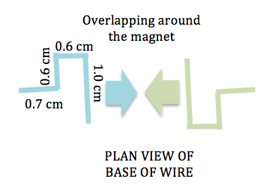
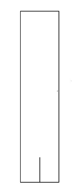
Make a V-shaped bend in the middle of the copper wire, with about 0.5 cm on both sides of the V-shape. Bend the copper wire into a rectangular loop using the dimensions shown below.
Tip: You may use the edge of a wooden block as a guide to bend the copper wires at right angles. A pair of wooden blocks can also be used to flatten the rectangular loop if you press them together tightly with the loop in between.
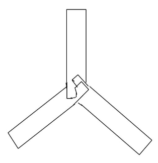
Mount the neodymium magnet(s) onto the magnet or iron base.
Hook the wires at the base around the magnets.
Place the AA-sized battery with the protruding end on the magnet(s).
Complete the electric circuit by placing the V-shaped end of the rectangular loop onto the flat end of the battery and watch the loop spin.
Be careful not to keep the current flowing for too long as the battery and wire can get very hot.
Science Explained
A force acts on a current if it is placed in a magnetic field. This force is what causes the motor to spin about its axis.
To apply Fleming's left hand rule, observe from the diagram below how the magnetic field bends around the magnet and its direction with respect to the direction of current flow. How do you think the loop will spin?
If you are having difficulty making this version of the homopolar motor, try the other design for the homopolar motor made using a screw.
A indoor boomerang can be constructed using 3 strips of cardboard put together. Throwing it may require some practice though but when you get the hang of it, it can inject great...
A indoor boomerang can be constructed using 3 strips of cardboard put together. Throwing it may require some practice though but when you get the hang of it, it can inject great fun into your lesson. You can explore using different types of material to get the best boomerang.
Materials
Cardboard about 1 mm thick, of suitable rigidity
Staples
Scissors
Rubber band or tape for added weight
Procedure
[caption id="attachment_349" align="alignright" width="159"] Cardboard strip with a slit cut[/caption]
Cut 3 equal rectangular strips of cardboard measuring 12 cm x 2.5 cm. You may like to trim the sharp corners on one of the ends of each strip.
Cut a slit of 1.5 cm along the middle of each strip, on the untrimmed end.
Join the strips together at the slits, the angle between two adjacent strips being 120 degrees.
[caption id="attachment_348" align="alignright" width="314"] 3 strips of cardboard overlapping each other[/caption]
One side of the slit should overlap another so that it looks like the above:
Staple the overlapping centre together.
The boomerang is ready for use! Throwing the boomerang is done by holding onto one of the wings. The boomerang should be almost vertical, at an angle of about 10o. With a flick of the wrist, spin the boomerang as it leaves the hand. The direction of spin should be toward the side that is tilted up.
Science Explained
A boomerang requires a centripetal force to cause it to fly in a circular path back to the thrower. This centripetal force comes from the lift that the wings generate as they cut through the air.