Problems involving two bodies moving together usually involve asking for the magnitude of the force between the two.
For example:
A 1.0 kg and a 2.0 kg box are touching each other. A 12 N horizontal force is applied to the 2.0 kg box in order to accelerate both boxes across the floor. Ignoring friction, determine:
(a) the acceleration of the boxes, and
(b) the force acting between the boxes.
To solve for (b) requires an understanding that the free-body diagram of the 1.0 kg box can be considered independently as only the force acting between the two boxes contributes to its acceleration since it is the only force acting on it in the horizontal direction.
This interactive app allows for students to visualise the forces acting on the boxes separately as well as a single system.
The codes for embedding into SLS:
<iframe scrolling="no" title="Two Mass Problem" src="https://www.geogebra.org/material/iframe/id/fh5pwc37/width/638/height/478/border/888888/sfsb/true/smb/false/stb/false/stbh/false/ai/false/asb/false/sri/false/rc/false/ld/false/sdz/false/ctl/false" width="638px" height="478px" style="border:0px;"> </iframe>
The following simulation allows users to observe the effect of air resistance on a parachutist before and after he opens his parachute. Try to open the parachute when the man first reaches terminal velocity and observe the changes in velocity.
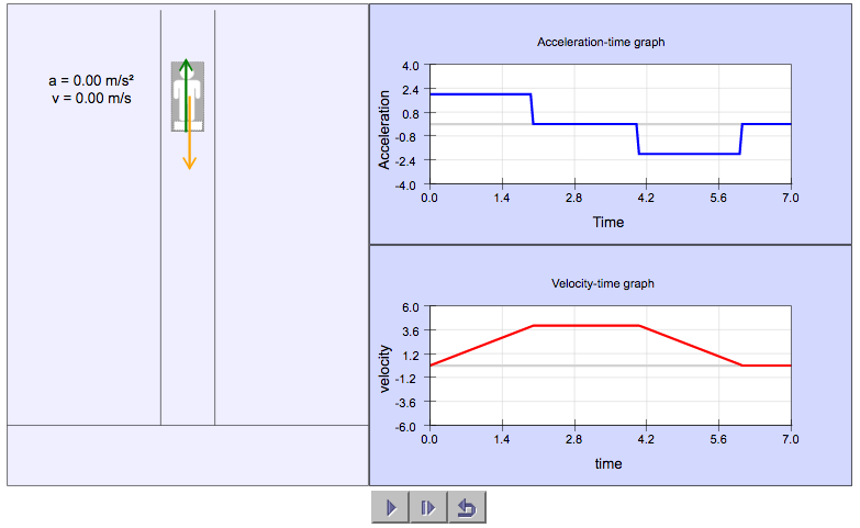
In this simulation, students can observe the variation of the normal contact force (N) and its effect on acceleration and velocity as an elevator moves upward.
Questions for students to work on can include:
Express the acceleration as a function of Normal Contact Force (N), Weight (W) and mass of the man.
Determine the distance travelled by the elevator.
Predict how the forces, acceleration and velocity will differ if the elevator was moving down instead.
For my students: To download the file and video for analysis using Tracker, right-click the file here…
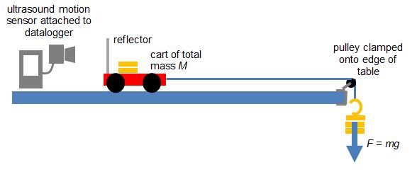
To verify the equation F = ma, where F is the resultant force on an object, m is the mass of the object and a is the acceleration, this is one of the ways to do so:
Equipment:
1. Motion Sensor
2. Datalogger
3. Cart with variable mass
4. End Stop
5. Pulley with clamp
6. Hanger Mass Set
7. String (about 1.2 m)
For a system of a cart of mass M on a horizontal track that is connected to a hanging mass m with a string over a pulley, the net force F on the entire system (cart and hanging mass) is the weight of hanging mass. F = mg (no friction assumed).
According to Newton’s Second Law, mg = (M+ m)a. We will try to prove experimentally that this is true in the video below.
In a recent IP3 class on Newton’s 2nd Law, the students were presented the “Elevator Problem” based on the THINK Cycle approach – a version of inquiry-based learning that was started in Temasek Junior College, Singapore.
The “Elevator Problem” is a physics phenomenon observed in an everyday experience that students can relate to quite easily. It is presented to our IP3 (K9 students) right after the introduction of Newton’s 2nd Law, with the students having a good understanding of the forces of weight and normal contact as well as what makes a resultant force.
TRIGGER
The THINK Cycle kicks off with a Trigger: a problem or phenomenon for which students have to solve or explain. In the “Elevator Problem”, the Trigger is the observation that as I stand on a bathroom scale in a lift going from one floor to another, the reading on the scale changes in such a way:
When the lift starts moving, the reading on the scale increases momentarily.
For most of the journey, the reading is constant.
When the lift is stopping, the reading on the scale decreases momentarily
The video below (taken by myself) shows what happens:
The students are supposed to work in groups to explain this observation and hence, to deduce whether the elevator is on its way up or down.
HARNESS
In the Harness stage of the THINK Cycle, students would work in groups to answer some guiding questions to help them arrive at a conclusion:
What are the forces acting on the boy?
Which of these forces are constant and which can change?
How does the motion of the lift affect the changing force?
What force is the weighing scale showing?
I find that providing students with a small portable whiteboard or a few pieces of rough paper is necessary for them to represent their ideas in diagram form, especially when the objectives of this activity is best achieved with the help of free-body diagrams.
INVESTIGATE
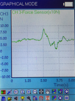
After coming up with a hypothesis based on their discussions, they will then seek to verify their hypothesis. Task number 2, which is for students to determine whether the elevator is going up or down, can be tested by hanging a 500 g mass on a force meter attached to a datalogger. We use the Addestation aMixer in our school, which is a handy portable datalogger with a plug-and-play range of user-friendly sensors. It gives us a graph that looks like that shown below when the mass is being pulled upwards, thus confirming that the movement of the elevator is also upward.
Variation of tension with time as the mass is pulled upwards.
The initial increase in tension acting on the mass is similar to that of the normal contact force on the man standing on the bathroom scale on the elevator. This is because both systems are accelerating upward.
The graph looks rather haphazard as the pulling is done manually and over a small height. By the time one pulls the mass up, he will have to decelerate already, which explains the dip in tension that follows right after the peak. Hence, we are unable to observe a stage where the tension is equal to weight, as we did for the scale in the elevator.
Nevertheless, students should be able to appreciate that a rise followed by a drop is observed for a mass being pulled upward.
NETWORK
For the sake of checking what the students have learnt collaboratively, each group is tasked to explain their observation and results on a A2-sized poster, with half the group staying at their own posters to answer questions while the other half going around to study the results from other groups. Their roles can be reversed after some time.
KNOW
In the final stage of our activity, the teacher will address the class and point out the common misconceptions that arose during the class discussions. For instance, many students are unaware that the upward force acting on the person standing on a weighing scale is the normal contact force and not the gravitational pull. This requires the teacher to introduce the terms “apparent weight” and “true weight” and making a distinction between the two.
After going through the topic of Dynamics in the A-level syllabus recently, it strikes me that there are several common mistakes or misconceptions that students whom I have taught over the years have always struggled with. I shall lay them out here in the hope that students who read this do not repeat the same mistakes.
1. Mixing up free-body diagrams involving multiple bodies in motion
Students are often confused about the forces in drawing free-body diagrams, especially so when they have to consider the different parts of multiple bodies in motion. A common mistake that students make is to draw all the forces, including the internal forces within a system, on a single diagram.
To solve a two-body dynamics problems, students need to learn how to draw the 3 possible free-body diagrams. A detailed set of instructions is found in an earlier post.
2. Adding instead of subtracting momenta to find impulse
Students who do not have a strong foundation in Math may not appreciate the fact that the addition and subtracting of vectors is not done by simply adding or subtracting the magnitudes. Sometimes, students are asking to find the force acting on an object when given the initial and final momenta. The correct way to find the vector of the change in momentum is to place the tails of the initial and final momenta together, and to join the arrowhead of the initial momentum with that of the final momentum with a third vector in that direction.
Vector triangle to find change in momentum
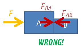
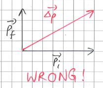
They are often confused between finding the change in momentum and the act of adding two vectors together. When that happens, what teachers see is the following triangle instead.
Wrong vector diagram to find change in momentum
While the magnitude of the vector found in both diagrams are the same, students will get the wrong answer if asked for the direction of the change in momentum. This is actually an important notion because the direction of change in momentum is really the direction of the net force applied on the body.
3. Using wrong signs for momentum for head-on collisions
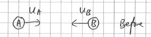
In A-level physics, in the study of collision problems, we will deal only with head-on collisions where two objects collide along the same line. Even then, students can get confused with the sign convention associated with the direction of motion of the objects.
Applying Conservation of Momentum
For a two body head-on collision problem, always start by writing down the following equation for the conservation of momentum:
[latex]m_Au_A +m_Bu_B = m_Av_A + m_Bv_B[/latex]
where [latex]m_X[/latex] is the mass of X, [latex]u_X[/latex] is the initial velocity of X, [latex]v_X[/latex] is the final velocity of X, where X is either A or B.
Follow this up by deciding on which direction you want to define as positive. For example, if you decide that the rightward direction is positive, the value of initial velocity for mass A is positive and that for mass B is negative.
What students sometimes do is to include the negative signs into the equation before substitution, e.g. [latex]m_Au_A +m_B(-u_B) = m_Av_A + m_Bv_B[/latex]. This causes confusion as they do not know where the directions of the final velocities are and hence, do not know which vectors to assign as negative.
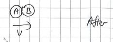
What we should do instead is to determine the final direction of the velocities after we have found the values. Before we are able to do so, we shall assume that the final velocities are to the right. If the final value of velocity of a mass is negative, it means that its final velocity is to the left.
Substitute the values into equation.
Assuming that the initial speeds are both 4.0 m s-1;, the mass of A is 3.0 kg, mass of B is 5.0 kg, and that the collision is perfectly inelastic, we have: